Three PLC Data Exchange Methods: Stale Data or Conflicting Commands
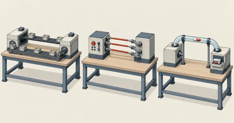
Which block to use to connect two PLCs is one of the last questions to ask. The first questions are whether that data needs to be fresh every scan and who owns the outputs it controls.
1-minute summary
- Symptom / problem
- Picking the wrong way for two PLCs to exchange data makes it slow or lets two sides drive one output.
- Who should read
- Control engineers who need two PLCs to talk to each other.
- Fix in short
- Tell the three apart, Data Link, Remote I/O and Message Service, and answer five questions on data freshness and output ownership before choosing.
I was designing data exchange between two PLCs in a test setup and noticed that I was calling everything "sending data back and forth." At the time, I thought the only question was which communication block to use. When I opened the Omron network manuals to find a basis for comparison, I saw that they separated PLC data exchange into three very different methods. Each has numerical limits, but more important than those numbers is that each answers the question of output ownership differently. I decided to write down this three-method framework and map it to the Siemens equipment I use.
First, I should state the level of evidence. All the Omron figures in this article come from manuals; I have not tested them on actual hardware. The manuals I used are the Controller Link Units Operation Manual (W309-E1-12) and the CS/CJ DeviceNet Units Operation Manual (W380-E1-10). Some figures come from training material from 2007 that I checked against the manuals. Page references are PDF file page numbers, not the numbers printed on the pages. The Siemens mapping is my own analysis, not something from an Omron manual. I will flag that again in the relevant section.
All three methods in this article exchange data for normal control. Safety interlocks, such as emergency stop buttons, safety doors, and light curtains, must use hardwired circuits or a dedicated safety system. The limits quoted apply to the equipment models covered by each manual. For actual work, consult the manual for the exact model and leave the decision to the engineer responsible for the machine.
The three methods distinguished in the manuals
Section 1-1 Overview of W309 describes the first two methods together. Data Link continuously shares data in predefined areas without requiring a communication program in the PLC. Message Service sends data to a particular node when needed, according to conditions, using communication instructions in the program. The third method appears in the DeviceNet manual: Master/Slave Remote I/O, where one side owns the logic and the other provides I/O.
Data flows automatically all the time
Define the areas once, and the network handles the rest. Both sides have their own programs and use data from the other side as input. Neither owns the other, so output ownership must be resolved in the program.
One side owns the logic
The Master decides, and the Slave follows. The Slave's outputs belong to the Master by design. Choosing this method settles the ownership question, and switches let you specify whether to hold or clear outputs when communication is lost.
The third method, Message, is absent from the comparison above because it is not a flow of data. It is one request at a time: send a command, wait for the reply, finish, then send again when the program issues another request.
Data Link: cyclic shared areas without a send program
Controller Link's Data Link runs on a token bus network. There are three speed-and-distance combinations: 2 Mbps at 500 meters, 1 Mbps at 800 meters, and 500 kbps at 1 kilometer. Each node can have 2 data link areas. Area 1 is accessed by bit, and area 2 by word.
There are two configuration methods, and the entire network must use the same one.
- Automatic Set the parameters in the PLC's DM, and it is ready to use. All nodes send the same amount of data. There are 4 patterns: Equality, 1:N common, 1:N 1-to-1, and 1:N chain.
- Manual Create a Data Link Table to define areas, sizes, and source nodes freely. Some nodes can send only or receive only, and a node can receive just part of the area sent by another node.
A common mistake during initial setup is that the mode and table must be set at the startup node. Without them, Data Link will not run at all. The example in the document I read is a three-node network: data in CIO 0 through 9 of node 1 appears in CIO 50 through 59 of node 2 and CIO 100 through 109 of node 3. I expressed that idea as JSON to show what information the table contains.
{
  "_note": "แนวคิดของ Data Link Table แบบ Manual เขียนให้อ่านง่าย ไม่ใช่รูปแบบไฟล์จริงของเครื่องมือผู้ผลิต",
  "mode": "manual",
  "must_be_set_on": "startup node",
  "links": [
    {
      "source_node": 1,
      "source_area": "CIO 0-9",
      "words": 10,
      "receivers": [
        { "node": 2, "area": "CIO 50-59" },
        { "node": 3, "area": "CIO 100-109" }
      ]
    }
  ]
}
The numerical limits depend on the unit model. This is where the older training material and the latest manual give different figures, which does not mean either is wrong; they simply cover different models.
According to PDF pages 6 and 31 of W309, -V1 models can send 1,000 words per node, CS/CJ units can send and receive a combined 12,000 words, and the network total is 32,000 words. CLK23 models can send 4,000 words per node, and CS/CJ units from Unit Ver. 1.2 onward can send and receive a combined 20,000 words. Section 1-5 Application Precautions in the same manual contains conditions that I consider more important than the figures: 4,000 words is available only with Manual data links, and if other unit models are present on the same network, the setting cannot exceed 1,000 words per node. Also, refreshing 20,000 words is split across three CPU scan cycles. The manual explicitly warns that this response time must be factored into the design.
That last point is what I mean by "stale data" in the title. Data Link does provide continuous data, but continuous does not mean up to date every scan. The more data you add, the longer the communication cycle becomes, and the PLC scan time increases along with it.
Master/Slave Remote I/O: one side owns the logic
I read about the second method in the DeviceNet manual. DeviceNet normally connects a Master to I/O devices, but a PLC's Master unit can also be configured to act as a Slave for PLC-to-PLC data exchange, and a single unit can be both Master and Slave at the same time. The result is that one PLC sees the other as an ordinary block of I/O.
There are two ways to allocate the areas.
| Item | Fixed allocation | User-set allocation |
|---|---|---|
| Master-side areas | OUT CIO 3200-3263 / IN CIO 3300-3363, 1 word per node, based on node number | 2 blocks each for OUT and IN, 500 words per block when set through Configurator |
| Total points | 2,048 points | 32,000 points |
| Number of Slaves | Up to 63 nodes | Up to 63 nodes |
| Areas when the unit is a Slave | OUT CIO 3370 / IN CIO 3270, 1 word each | Up to 100 words per block |
With fixed allocation, data locations are tied directly to node numbers. Word n corresponds to node n, so the calculation is straightforward.
def fixed_alloc(node):
    """Fixed allocation ชุดแรกของ DeviceNet master: word n = node n โหนดละ 1 word"""
    if not 0 <= node <= 63:
        raise ValueError('node address ของ DeviceNet คือ 0-63')
    return f'node {node:2d}: OUT CIO {3200 + node} / IN CIO {3300 + node}'

for n in (0, 1, 2, 63):
    print(fixed_alloc(n))
# node  0: OUT CIO 3200 / IN CIO 3300
# node  1: OUT CIO 3201 / IN CIO 3301
# node  2: OUT CIO 3202 / IN CIO 3302
# node 63: OUT CIO 3263 / IN CIO 3363
The strength of this method is not the amount of data, but two questions it answers from the start. First, logic ownership is clear by design: the Master makes decisions, and the Slave provides I/O. Second, behavior on communication loss can be configured with the DIP switch on the front of the unit: whether the Slave holds or clears its outputs, and whether the Master continues or stops communication when an error occurs. I have already covered the switch settings and what a custom link needs to implement in their place in the PLC-to-PLC link inspection checklist, so I will not repeat them here.
Message Service: individual requests followed by replies
The third method uses three ladder instructions: SEND(090) sends data to be written at the destination node, RECV(098) requests data from another node and stores it locally, and CMND(490) sends any FINS command. These are the SEND figures I collected.
| SEND parameter | Range |
|---|---|
| Words per request | 0-990 words |
| Destination node | 1-62 (FF is broadcast) |
| Retry count | 0-15 retries |
| Internal CPU port | 0-7 |
| Response wait time | 0.1-6553.5 seconds |
| Maximum message length | 2,012 bytes |
I confirmed the 0 to 990 words range and FF broadcast against PDF page 194 of W309. The same page has a note worth reading in full: message service does not guarantee that a message will reach its destination; noise can cause it to be lost along the way. The manual therefore recommends setting the retry count to a value other than 0.
At this point, I saw where my previous understanding had been wrong. I used to think that if I wanted data from another PLC, I could simply keep issuing read instructions and get the same result as Data Link. But it is not the same. Each request must reserve one of 8 ports, wait for a reply, handle a missing reply, and only then issue another request. Data therefore arrives at intervals determined by the requesting program's cycle, not the network cycle. If it is used to decide outputs every scan, the program will make most of those decisions using old values. The manual's selection rule is therefore very short: Data Link when data is needed continuously, Message when sending or receiving on individual occasions.
CMND can send every type of FINS command, including commands that change the destination CPU's operating mode. The example in the document I read uses CMND to send command 0402 to another node, causing that node's CPU to switch to PROGRAM mode. This means any node on the network can stop another PLC unless there are restrictions on which programs may use this command. Details are in the article on FINS commands.
Mapping these to Siemens: my own analysis
This section does not come from an Omron manual or any Siemens manual that provides such a comparison. It is my own mapping based on what each method does. It is reasonable for others to disagree.
| Omron method | Siemens option with a similar role | Differences |
|---|---|---|
| Data Link | Cyclic transfer of an entire DB with TSEND_C/TRCV_C | A custom Data Link; per-node status and heartbeat must be implemented separately |
| Message Service | PUT/GET or individual read/write operations | Requests occur when the program issues them; data does not flow automatically |
| Remote I/O Master/Slave | I-Device, Shared Device, or directly wired I/O | Ownership is clear at the structural level |
The first row is the one I need to be most careful with. Sending a DB cyclically over TCP feels just like Data Link, but the features that an actual Data Link provides, such as whether each node is still present and whether its program is running, do not come with it. All of that must be implemented separately.
Another point is that I can choose cyclic DB transfer while giving one side ownership of the logic, as in Remote I/O. The owner writes commands into the data block, and the station side only copies those commands to the physical outputs at a single point, with no decision-making logic of its own. This uses a Data Link-style transport with a Master/Slave division of responsibilities. An implementation example is in the article on moving I/O to remote I/O over a TCP link.
Five questions for choosing a method
Before opening the programming software, I answer these five questions on paper.
- Is this data used to decide outputs every scan, or is it reporting data? If it is needed every scan, rule out Message immediately.
- Who owns the logic for that actuator? The basic rule is never to write to the same output from two places. If two PLCs each have logic commanding the same valve, that is the situation this rule warns about.
- When communication is lost, should the outputs hold or clear, and who confirms that decision?
- Do the data volume and cycle time fit within the chosen method's limits, and is the actual cycle time fast enough for the process?
- Is this data part of a safety interlock? If so, it must use hardwiring or a safety system, not a data link.
Question 2 is where "conflicting commands" in the title comes from. If I choose Data Link and let both sides use their own logic to decide the same output based on data from the other side, I get a system where two controllers overwrite each other's commands, with behavior depending on which one writes last in a given cycle. I turned the five questions into a short function to check my own thinking. The order of the conditions is what I want to show: safety first, ownership second, and technical details after that.
def choose(safety_related, single_owner, every_scan, on_loss_defined, words):
    if safety_related:
        return 'สายแข็งหรือระบบ safety ไม่ส่งผ่านลิงก์ข้อมูล'
    if not single_owner:
        return 'หยุดก่อน ยังมี logic สองที่สั่งเอาต์พุตตัวเดียวกัน'
    if every_scan and not on_loss_defined:
        return 'หยุดก่อน ยังไม่ได้ตกลงว่าลิงก์ขาดแล้ว hold หรือ clear'
    if every_scan:
        return 'remote I/O หรือ data link วนรอบที่มีตัวบอกความสด'
    if words <= 990:
        return 'message เป็นครั้ง ตั้งจำนวนครั้งส่งซ้ำไม่ใช่ 0'
    return 'เกิน 990 words ต่อครั้ง แบ่งส่งหลายรอบหรือย้ายไป data link'

print(choose(False, True, True, True, 40))
print(choose(False, True, False, True, 1500))
print(choose(False, False, True, True, 40))
Then I save the answers in a file with the project so that whoever takes over knows why I chose this approach.
exchange: Main_PLC -> Station_A
purpose: คำสั่งขับเอาต์พุตของสถานี
used_every_scan: true
logic_owner: Main_PLC          # Station_A คัดลอกคำสั่งออกเอาต์พุตอย่างเดียว
on_link_loss: clear            # ยืนยันโดยผู้รับผิดชอบเครื่อง ลงชื่อและวันที่ในเอกสารแยก
safety_interlock: false        # ของจริงเดินสายแข็ง ไม่อยู่ในก้อนข้อมูลนี้
pattern: remote-io-over-cyclic-db
size_words: 40
Limitations of this article
The supporting training material I used is from 2007, and the equipment models are from that period. For every figure used in a design, follow the official manual for the exact model purchased. As the Data Link section shows, simply changing the unit model raises the limit from 1,000 to 4,000 words per node. I collected the Fixed allocation, User-set allocation, and SEND parameter figures from the documents I read. Some tables in those documents are images, and pages I did not open may contain conditions I have missed. I have not tested any of this on actual Omron hardware.
To conclude, these three methods do not compete with one another; they answer different questions. Data Link addresses data that must always be available. Remote I/O addresses who owns the outputs. Message addresses individual operations. They can, and should, be combined within a single system. Personally, if a block of data ultimately controls machine outputs, I always start by choosing a structure with a single owner. For reporting data or values read only occasionally, I use whichever method is convenient. If I have mapped anything incorrectly or misread a manual, I will come back and correct it later.
Hit something like this? Stuck somewhere?
Come trade notes on the LinuxThai board
Comments 0
No comments yet — be the first