Thai Steel Framing Conventions for Buildable Drawings

A steel frame model usually goes wrong on conventions, not mathematics—stacking order, sections that are actually sold, and the choice of bearing edge on sloping beams. A fabricator can see at a glance that it cannot be assembled, even when every line matches the numbers exactly.
Lately I have been modeling steel frames on the computer quite often, both drawing them myself and asking AI to draw them, and I keep running into the same problem: the model looks good, every dimension matches what I asked for, but when I show it to a fabricator, they can point out what cannot be built within ten seconds. So I went through the mistakes one by one and found that none of them were calculation problems. They were all site conventions that fabricators know without being told, but people drawing on a computer do not, so I collected them into a set of rules.
This article is purely about fabrication conventions, not strength calculations. I have already covered force analysis and heatmap coloring separately in the FEA article.
The section sizes, distances, and angles given here are only values used to explain assembly conventions. They are not design results. Any structure that actually carries loads, whether a carport roof, an awning, or a house extension, must always have its calculations completed and signed off by a licensed engineer before construction. Do not use the numbers in this article to order steel cuts.
Always read the load path from top to bottom
Before drawing the first line, I need to know how the load reaches the ground, because that sequence determines what sits on what, which in turn sets the elevations of every member throughout the frame.
There is one short rule: each layer sits with its full section above the layer below. Written as an equation, the bottom surface of the upper member equals the top surface of the lower member. Nothing passes through anything else, floats above it, or embeds itself into it. If someone models everything at the same elevation and lets the members intersect, that is a cart frame, not a roof frame. A fabricator will flag it immediately.
The terms "joist" and "rafter" vary from place to place. I always use the term the client uses. If they call it a joist, I call it a joist; there is no need to correct them, because ultimately their fabricator is the person who has to read the drawings.
Standard sections a fabricator can pick from stock
The most common mistake people make when drawing on a computer is choosing arbitrary section dimensions, such as making a beam 140 x 80 because the calculation works out. The problem is that steel suppliers do not sell it. What they have in stock comes in sizes named in inches and converted to millimeters. So I fix the set of sections at the start and design around what is available.
These numbers come directly from nominal inch sizes rounded to millimeters: 6 inches is 150, 3 inches is 75, 4 inches is 100, and 2 inches is 50. I use these exact millimeter values rather than converting with 25.4, because this is how fabricators and steel suppliers refer to them. The steel grades found here in Thailand are formed hollow sections to TIS 107 (STKR400), hot-rolled steel to TIS 1227 (SS400), and cold-formed C sections to TIS 1228 (SSC400). Specify the TIS standard when ordering, or the steel may arrive thinner than expected. A specified thickness of t2.3 and an actual measured thickness of 2.0 mean different prices and different strengths.
Box section means a hollow square or rectangular section, used for beams and joists · Steel pipe means round sections only; do not call square or rectangular steel sections pipe · Flat bar means flat steel a few millimeters thick, used for plates and fasteners. I once used the wrong term on a purchase order, and the supplier delivered a whole pile of round sections. Exchanging them cost two days.
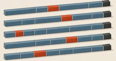
Another point that directly affects the design is that one stock length of steel is 6 meters long. If a member is longer than 6 meters, it needs a splice, which is possible, but the splice must be in the right place: over a supporting beam, not at midspan. So I like to design the longest member in the frame to end at exactly 6.00 meters. There is little scrap, no splice, and the fabrication is straightforward.
Stack, do not interweave
This is the issue fabricators have flagged to me most often. When two beams meet at a building corner, people drawing on a computer often put both at the same elevation and let them intersect at the corner. It looks seamless on screen, but real steel members cannot occupy the same space at the same elevation. One must sit above the other, and the upper member must overlap with its full section, not just half of it.
Stacking
- Beam A runs continuously at its own elevation
- Beam B is raised by one beam depth and sits on top with its full section
- The beam sits on the column head; the column head does not protrude through it
- The outer face of the beam is flush with the outer face of the column
Interweaving
- Two beams sit at the same elevation and pass through each other
- Steel volumes overlap at the intersection, making actual welding impossible
- The column passes up through the beam, leaving it too tall
- Referencing centerline grids leaves the outer faces offset at every corner
Position references matter just as much. Fabricators conventionally reference the outer corners or outer faces of the building, not member centerlines, because on site they set string lines along the outer faces. If I reference centerlines in the model, stacking multiple layers accumulates an offset of half a thickness at a time. After five or six layers, the error reaches centimeters.
Another point is that steelwork uses welding; it is not timber construction that needs notched joints. Joists spanning beams simply sit in contact and are welded in place. There is no need to notch the joist to fit the beam. If I accidentally model a notch, the fabricator will ask why I want it notched. It just wastes time.
Purlins are open C sections, not solid boxes
Purlins are the members most often modeled incorrectly, because people tend to start by drawing a solid rectangle, which is wrong in two ways. The first is the section: a purlin is a C section with flanges turned inward to form lips, leaving an open mouth rather than a closed box. The second is orientation: the purlin must tilt perpendicular to the roof surface, not stand vertically, or the roof sheet will sit on just one edge of the purlin.
# หน้าตัด C มีลิป 100x50x20 หนา 2.3 — 12 จุด วนตามเข็ม แล้วค่อย pushpull เป็นความยาว
mm = 1.0 / 25.4                       # SketchUp คิดเป็นนิ้วภายในเสมอ
cw = 100 * mm                         # ความลึกเอว (web)
cf = 50  * mm                         # ความกว้างปีก (flange)
cl = 20  * mm                         # ลิปพับกลับ
ct = 2.3 * mm                         # ความหนา

cprofile = [[0,0],  [cf,0],     [cf,cl],       [cf-ct,cl],
            [cf-ct,ct],         [ct,ct],       [ct,cw-ct],
            [cf-ct,cw-ct],      [cf-ct,cw-cl], [cf,cw-cl],
            [cf,cw],            [0,cw]]

grp  = Sketchup.active_model.entities.add_group
face = grp.entities.add_face(cprofile.map { |u, w| Geom::Point3d.new(u, 0, w) })
face.pushpull(-purlin_len)            # ยืดไปตามแนวความยาวแป

# เอียงแปให้ตั้งฉากผิวหลังคา หมุนรอบแกนความยาวของตัวมันเอง
theta = Math.atan2(roof_rise, roof_run)
grp.transform!(Geom::Transformation.rotation(grp.bounds.center, axis_along_purlin, -theta))
Why does it have to be an open C section? It is not just about appearance. It affects three things in practice. First is weight: a C section uses far less steel than a solid box of the same depth. Second is driving screws down through the roof sheets: they need a top flange to engage. Third, if the model uses a solid box, whoever calculates the steel quantities will get a weight far above the actual value, and the quotation will be wrong too.
Members resting on sloping beams need the correct bearing edge
This is the trap that cost me the most time. Suppose a single straight joist spans from the low-side beam up to the high-side beam. The joist is straight, and both beams follow the outer face lines. The question is which beam edge the joist touches. The answer is not the same edge on both sides.
A straight joist sloping upward always touches a beam at its "top corner on the downslope side." On the low side, that corner is the outer edge, but on the high side, it is the inner edge. If I use the outer edge on both sides, the joist penetrates the high-side beam by roughly ten to fifteen millimeters. Fabricators call this overlapping or piercing through, and will reject it immediately. If I correct it too far the other way, the joist floats above the beam without touching it.
# เส้นใต้ตง = เส้นที่ลากผ่าน "มุมบนด้านต่ำ" ของคานทุกตัวที่มันพาด
# ฝั่งต่ำ  ใช้ขอบนอก  x = 0
# ฝั่งสูง  ใช้ขอบใน   x = span - beam_width      <- จุดที่คนพลาด
run = span - beam_width                      # ระยะจริงของเส้นใต้ตง ไม่ใช่ span เต็ม

joist_bottom = lambda { |x| z_low + (z_high - z_low) * x / run }
center_z     = joist_bottom.call(x) + joist_depth / 2.0
Notice that the denominator is span - beam_width, not span. This is a tiny detail, but it changes the actual slope along the entire member. If I use the full span and then measure at the other end, I find an offset of millimeters.
Two traps when placing members on an already tilted member
Once the joists follow the roof slope, placing purlins on top involves two calculations people often get wrong. Errors in either leave elevations off by 1 to 15 millimeters, enough for a fabricator to see with the naked eye.
A joist of depth rd tilted at an angle theta has its top surface vertically above its centerline by rd/2 divided by cos(theta), not simply rd/2, because the half-depth distance is perpendicular to the member, not to the ground. Using rd/2 directly makes the purlin sink into the joist by rd/2 times (1/cos(theta) minus 1). Every additional layer stacked above adds to the error.
The second trap is the position reference. When placing a purlin flush with the end of a joist, people often put the purlin's centerline at the joist end. This leaves half the purlin hanging beyond the joist. The correct reference is the finished edge, meaning the purlin's outer downslope edge, and the distance from the centerline to that edge after tilting is
# ระยะจากแกนกลางแป ไปถึงขอบนอกด้านต่ำ หลังเอียงไปแล้ว theta
edge_off = (cf / 2.0) * Math.cos(theta) + (cw / 2.0) * Math.sin(theta)

# ตำแหน่งสัมผัสจริงบนตง ก็ขยับไปจากที่คิดไว้ด้วย
contact_x = nominal_x + (cw / 2.0) * Math.sin(theta)

# ผิวบนของตงที่จุดสัมผัสจริง (กับดักข้อแรก)
seat_z = joist_bottom.call(contact_x) + (rd / 2.0) / Math.cos(theta)
The short rule I use to remind myself is that, for every layer stacked on something already tilted, its thickness does not add that same amount to the vertical height. It always adds the thickness divided by the cos of the slope angle.
Purlin spacing comes from the roof sheets, not the person drawing
I have made this mistake myself. At first, I calculated the purlin spacing by dividing the slope length by the number of purlins I wanted, which gave 962 millimeters. It looked tidy. It turned out to be unusable, because roof sheets are manufactured products that cannot be resized. The sheets themselves already determine the purlin spacing.
A standard double-wave roof sheet is 120 centimeters long and needs a 20-centimeter end lap to prevent water from backing up underneath, leaving exactly 100 centimeters of usable coverage per row. That means fixed purlin spacing of 1.00 meter. Place the first row at the eaves and work upward in 1.00-meter increments. Only the topmost row can be moved to support the ridge cap.
- Set purlin spacing to 1.00 meter to match the roof sheet module. Do not calculate your own spacing to fit a chosen number of purlins.
- Adjust the building dimensions so the slope length is a whole multiple of 1.00 meter, rather than adjusting the roof sheets.
- Allow the sheets to overhang the outermost purlin at the eaves by 10 to 15 centimeters. Any more leaves the sheet ends too flexible and prone to cracking.
- Lay the sheets from bottom to top, completing each row before moving to the next. Always start on the leeward side.
- Overlap sideways by 1 wave. The effective coverage width is 45 out of 50 centimeters; use this value to calculate the sheet count.
- Drive screws only through the wave crests directly over purlins. Never screw through the drainage valleys, and never step on the middle of a sheet.
For double-wave cement roof sheets, manufacturers recommend a minimum slope of 15 degrees. Below that, wind can drive water back under the sheets even with a longer overlap. If the client insists on a lower slope because of height constraints, I follow their drawing, but also note on it that the slope is below the manufacturer's recommendation and let them make the decision.
Measure the gaps before calling the work finished
Before handing over the drawings, I check every joint the same way a fabricator would. The fastest method is to pull out the numbers directly instead of judging by eye. For axis-aligned joints, the required value is exactly zero. Positive means a gap; negative means an overlap.
# ตรวจระยะห่างของทุกคู่ที่ควรวางซ้อนกัน ค่าที่ยอมรับคือ 0 เท่านั้น
pairs = [["col_",   "beam_"],      # เสา -> คาน
         ["beam_",  "post_"],      # คาน -> เสาค้ำ
         ["post_",  "topbeam_"]]   # เสาค้ำ -> คานรับตง

pairs.each do |below_p, above_p|
  b = groups_with_prefix(below_p).first
  a = groups_with_prefix(above_p).first
  gap = a.bounds.min.z - b.bounds.max.z
  mmgap = (gap * 25.4).round(2)
  status = mmgap.abs < 0.01 ? "pass" : (mmgap > 0 ? "FAIL ลอย" : "FAIL กินกัน")
  puts "#{below_p} -> #{above_p} : gap=#{mmgap} mm  #{status}"
end

# ตรวจหน้าตัดกับความยาวไปในรอบเดียวกันเลย จับขนาดผิดได้ทันที
groups_with_prefix("beam_").each do |g|
  dx = ((g.bounds.width)  * 25.4).round(1)
  dz = ((g.bounds.height) * 25.4).round(1)
  puts "#{g.name}: #{dx} x #{dz} mm"     # คาน 6x3 ต้องได้ 75.0 x 150.0 ทุกเส้น
end
Sloping joints cannot be checked using bounds values, because they touch along only a line or at a corner. The bounding box tells me nothing. I need close-up orthographic renders looking along the members, then inspect each bearing point—the low side, the middle, and the high side—in three separate images, visually confirming that the joist touches the correct edge and the purlin actually sits on the joist surface, neither floating nor sinking into it.
I stopped building the whole frame in one pass and checking afterward, because an error in a lower layer propagates through every layer above, leaving eight places to fix at once. I switched to one script per layer, with each script deleting its own group before rebuilding it so repeated runs never create overlapping copies. After completing a layer, I render it for inspection, count the members, and only then move to the next layer. It is slower at the start, but much faster overall.
Personally, I think these conventions are far more valuable than people who build models tend to realize, because they are the language used to communicate with fabricators. With drawings that follow the conventions, a fabricator can open them and order the steel cuts without having to call with questions. With drawings that look good but break the conventions, the fabricator ends up making changes on site in whatever way they are used to, and what actually gets built is no longer what I drew. Feel free to adapt this set of rules to your own site. If I have left anything out or made a typo, I will come back and correct it later.
Hit something like this? Stuck somewhere?
Come trade notes on the LinuxThai board
Comments 0
No comments yet — be the first